There are many testing methods to evaluate the flammability of cables. The vertical tray flame test (method 1 - vertical tray and method 2 - FT4) of UL 2556 9.6 is one of them. A cable tray (ladder to fix cables to) is placed vertically in a combustion room with inner dimension 2440Wx2440Dx3350H. Cable specimens are tied in a row. A large propane burner placed at the bottom of the tray is used to burn the bottom of the cable for 20 minutes, and we observe how much of the specimens have burned.
This test evaluates whether a fire that occurred in some floor transfers through cables in the cable tray to the topmost floor. The ventilation is regulated as 0.65 m^3/s to control the amount of oxygen supplied during the test. (Note 1)
In consequence, the amount of ventilation must be measured. UL 2556 Annex H defines that the velocity in the ventilation duct need to be measured using with a slightly strange differential pressure flowmeter (Note 2), and that the velocity is derived with the equation
  V = 0.806 * ΔP * Tk
  Here,
	V = Velocity (m/s)
	ΔP = Differential pressure of sensor (mmHg)
	Tk = Temperature of measured air (K)
Someone with some knowledge or common sense of engineering feels that this equation is strange. I asked the technical team of UL Japan why this equation is valid, and the response was "flow rate is indeed proportional to (differential pressure x temperature)". Both the engineer that responded and a senior engineer had the same opinion. Therefore, this is the official response from UL.
Is the UL standards and UL Japan correct with their statement that for a differential pressure flowmeter, flow rate is proportional to (differential pressure x temperature) ?
This is the question.
Note 1 - Errors in regulated flow rate
There is a significant inconsistency in the tolerance of flow rate.
Note 2 - Differential pressure flowmeter
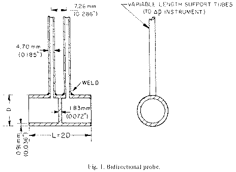
The differential pressure flowmeter is one of the most basic tools to measure flow rate. Based on Bernoulli's theorem, which is one form of the energy conservation principle, an obstacle to prevent flow is placed in a section of the duct, and the flow rate is derived from the difference in pressure before and after the obstacle. There are a number of methods to generate differential pressure, and orifices are typically used. This standard uses a short cylinder where a plate is used to block the center, as shown in the figure below. In other words, we use a structure where a disc is placed to block air flow, and cylinders are placed before and after the disc. This structure is placed in the center of the 16 inch diameter duct.
