
Fig. 1 - Transmission circuit terminated with characteristic impedance
It is well known that the relation between input voltage and output voltage of a transmission circuit terminated with characteristic impedance can be expressed using the propagation constant γ and length of the transmission line.
  E2/E1 = exp(-γ*l)                                       (1)
  Here,
	E1 = Input voltage (V)
	E2 = Output voltage (V)
	l = Length of line (m)
	γ = Propagation constant
	   = sqrt((R + j*ω*L)*(G + j*ω*C))
	R = Conductor resistance of line (Ohm/m)
	L = Inductance of line (H/m)
	G = Conductance of line (S/m)
	C = Capacitance of line (F/m)
	ω = 2*π*f .. Angular frequency
	f = Frequency (Hz)
	π = 3.14159..
Most of the conductance G originates from dielectric loss;
  G = ω * C * D
  Here,
	D = dissipation factor of dielectric (tanδ)
	  = (Energy lost in 1 cycle) / (Energy accumulated in C).
The physical meaning is energy lost in molecular vibration, which is observed in microwave ovens, therefore is very small in materials with small polarization, such as polyethylene, tetrafluoroethylene, or air, and is zero in vacuum. Therefore, G can be ignored in standard high frequency cable because ω * C >> G holds.
Conductor resistance R arises from eddy current loss such as the skin effect of conductors. This quantity is roughly proportional to the square root of the frequency, and is responsible for most of the attenuation in cables.
The frequency dependence on the capacitance C and inductance L is very small, and can be usually regarded as constant values. However, in pulse transmission, the extremely small frequency-dependent properties of L from eddy currents in the conductor have significant effects on the transmitted waveform.
When E1 is a sinusoidal wave,
  γ = α + j*β
  Here,
	&alpha = Attenuation constant (neper/m)
	&beta = Phase constant (rad/m).
The attenuation constant and phase constant appears in the simple relation
E2 / E1 = exp(-α*l)*exp(-β*l)Compared to E1, the output voltage E2 has amplitude decreased by a factor of exp(-α*l) and phase delayed by exp(-β*l). The properties of cables are typically shown as the attenuation constant and the velocity ratio. (Note 1).
In general, the attenuation of cables is inversely proportional to the conductor diameter and is proportional to the square root of the frequency. Therefore, the output voltage decreases when the conductor is thinner and the frequency is higher. In any case, the output voltage decreases with increasing attenuation.
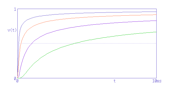
On the other hand, when E1 is a pulse wave, the step response of the time axis is considered in place of frequency characteristics. The step response of coaxial cables with the same length but different attenuation is as follows:

Fig. 2 - Step responses of coaxial cables with the same length but different attenuation
These characteristics are those of high quality high frequency cables with G = 0, and matches the waveform observed with an oscilloscope.
The top curve corresponds to the cable with the smallest attenuation, and the attenuation of the second, third, and fourth curves from the top is two, four, and eight times that of the top curve.
The output voltage decreases in cables with large attenuation with a step response as with sinusoidal waves.
What happens to the output voltage from a step response when infinite time has passed ?
This is the question.
Kouichi Hirabrayashi (C) 2008
Note 1 - Phase constant and velocity ratio
The phase constant is given as
  Phase constant = 2*π*f/vp
  Here,
	vp = Phase velocity (m/s)
The frequency characteristics of phase speed is very small, therefore the phase speed is normalized with the speed of light in vacuum (which is the fastest speed that is achievable) and given as the "velocity ratio" (phase velocity divided by the speed of light in vacuum) that is independent of frequency. Some people use the "shortening coefficient of wavelength" (the wavelength in cable divided by the wavelength in vacuum) obtained using the relation "phase constant = 2*π/wavelength".
Standard high frequency cables satisfy
G << j*ω*CTherefore it is safe to ignore G and use
E2/E1 = exp(-l*sqrt((R + j*ω*L)*j*ω*C)) (2)When E1 is a step input (Heaviside unit function)
  E1 = 1   (0 <= t)
     = 0   (t < 0)
(2) can be solved analytically if R, L, and C in (2) are constants:
  E2/E1 = exp(-R/2/L*t)*I0(R/2/L*sqrt(t^2 - L*C*l^2))  (sqrt(L*C)*l <= t)
	= 0 (t < sqrt(L*C)*l)
  Here
	I0(x) = 0th-order modified Bessel function
The solution is a combination of a Bessel function and an exponential function. However, in real cables, the frequency characteristics of R arising from eddy current loss from the skin effect of conductors and the frequency characteristics of the internal inductance (inductance from magnetic flux in a conductor), which is the cause of phase distortion in L, are both large. This analytical solution is close to reality but clearly different.