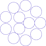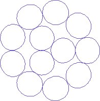
Fig. 1 Example of cable cross-section schematic
The structure of many cables, such as cylindrical cables and twisted-wire conductors, is cylindrical wires twisted together. For a figure of the cross-section, a combination of true circles is used including figures used at our company.

Fig. 1 Example of cable cross-section schematic
For example: Fig. 1 shows a typical cable structure. A 12-core cable with equal strand diameters is shown, where three strands twisted together is used as a core and twisted together with nine strands. If the twist pitch is infinitely long, and cylinders were placed in parallel, the cross-sections will indeed be circular. However, actual cables are made of twisted cylinders, and therefore the cross-section of strands will not become "circles" and would not become even "ellipses", the cross-section when cylinders are cut at an angle.
In other words, figures of this kind do not show the actual cross-section of the products, but is only a schematic to show the approximate configuration. For the structure in the example, since this is a twisted structure, the strand cross-sections will never be true circles, including the three strands in the core. And in reality, there is almost no gap between the strands in the outer layer.

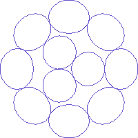
Fig. 2 Actual cross-section of the twisted wire shown in Fig. 1
The actual cross-section is as shown in Fig. 2. Note that the strands have a somewhat distorted circular structure that at first glance seems elliptical, and there are no gaps between the strands in the outer layer.

Fig. 3 When one strand in the outer layer is removed
In actual cables, when many strands with the same size are bunched together in a concentric manner, with some exceptions, the number of strands in each layer is six more than the layer directly inside. If the number of strands in a layer is five more than the inside layer, we obtain a cable as shown in Fig. 3, and we can well understand the distortion in the cross-section.

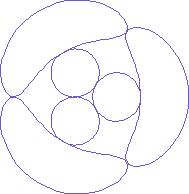
Fig. 4 A more extreme case
In a more extreme case, the wires are more coiled than twisted. If the number of strands in the outer layer is chosen to be the same as the inner layer, the distortion is like the picture shown in Fig. 4. The outer strands look close to an ellipse in Figs 2 and 3, but now the shape is completely different from that of an ellipse.
The cross-section of twisted strands takes what shape? Can this be described by analytic geometry at the high school level, or do we need more advanced mathematical tools? Furthermore, can we consider the shape as an ellipse when the distortion is small ?
These are the problems.
Kouichi Hirabayashi, (C) 2006