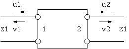
Fig. 1. Two-port circuit inserted between two transmission lines
"S-parameters" are a convenient concept when handling high frequency currents. For a two-port (four-terminal) circuit inserted between two transmission lines with characteristic impedance as shown in Fig. 1, the definition is as follows.
Fig. 1. Two-port circuit inserted between two transmission lines
  [ v1 ]   [ S11  S12 ][ u1 ]
  [    ] = [          ][    ]
  [ v2 ]   [ S21  S22 ][ u2 ]

  here,
	u1 = Voltage of incident wave to port 1 (V)
	u2 = Voltage of incident wave to port 2 (V)
	v1 = Voltage of reflected wave from port 1 (V)
	v2 = Voltage of reflected wave from port 1 (V)
S11 is the ratio of incident wave to reflected wave at the input terminal when there is no incident wave to the output terminal (port 2). Thus it is called the "voltage reflection coefficient" of the input terminal (port 1). S21 indicates how much voltage is transferred to the output terminal when a wave with a voltage u1 is incident at the input terminal, and is named the "voltage transmission coefficient".
Similarly, S22 and S12 are the voltage reflection coefficient and voltage transmission coefficient of the output terminal. If the characteristic impedance of the transmission lines on both ends are equal, and the two-port circuit is electronically symmetric (looks the same from any direction), S11 = S22 and S12 = S21.
The basic function of the "Network Analyzer", one of the most fundamental electron measurement devices in modern times, is to obtain the "S-parameters" from direct measurements of incident, reflected, and transmitted waves based on a combination of directional couplers and a precise calibration mechanism, For example, when S11 is measured by connecting a 75 Ohm coaxial cable approximately 1.5 m long to a common 50 Ohm network analyzer, the following results were obtained.
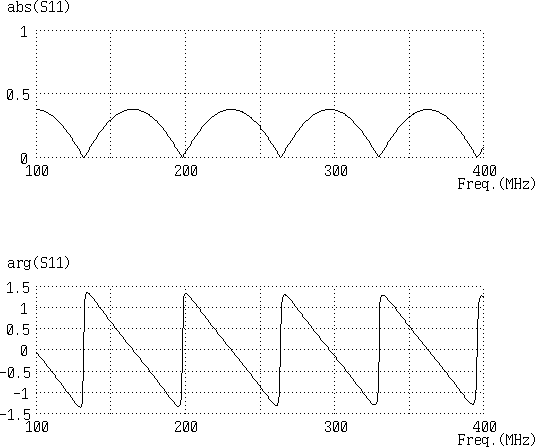
Fig. 2 Measurement example of S11 using a network analyzer
The results suggest that the voltage reflection coefficient of a coaxial cable has a frequency dependency, and there are infinite frequencies with no or very little reflection.
On the other hand, for the voltage reflection coefficient with the same definition, in transmission line theory, the voltage reflection coefficient of port 1 is
  (Z0 - Z1) / (Z0 + Z1)
	= (75 - 50) / (75 + 50)
	= 0.2
This value is constant regardless of frequency, and since Z1 != Z0, the no reflection condition is not satisfied.
Where does this discrepancy arise from ? Why do we obtain no reflection results where characteristic impedance is discontinuous ?
Kouichi Hirabayashi, (C) 2003