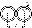
Fig. 1 Return circuit made of bare conductors

Fig. 1 Return circuit made of bare conductors
The dielectric constant of a twin lead consisting of bare conductors can be calculated easily as shown below. (Footnote 1)
C = 2*PI*e/acosh((D^2 - 2*a^2)/2/a^2) (1) Here, C = capacitance (F/m) a = radius of conductor (m) D = distance between conductors (m) PI =█× 3.14159265358979.. e = dielectric constant (F/m) = es*e0 es ┼ü= relative dielectric constant e0 = dielectric constant of vacuum (F/m) = 1e7/4/PI/c^2 c = light of speed in vacuum (2.998e8 m/s)acosh(x) is the inverse hyperbolic cosine function, and can be written with the logarithmic function asĪó
acosh(x) = log(x + sqrt(x*x - 1))In the limit where the distance between conductors is large (a << D), the well known approximation
C = 2*PI*e*log(D/a)holds. The error is less than 1 % when D/a = 2.7, and less than 0.1% when D/a = 4.3.

Fig. 2 Return circuit made of insulated conductors
In reality, actual cables require the use of insulators, and therefore a setup as shown in Fig. 2 is more natural and general. However, if adding insulators complicate the calculations tremendously and only an approximate value is necessary, a concept named effective dielectric constant may be used.
With this concept, an apparent relative dielectric constant ee ®üis us d that can be used in equation (1) even though the system has multiple dielectrics, such as polyethylene and air. Although this apparent dielectric constant can only be obtained by accurate calculations or by actual measurement, it is clear that this value is somewhere between the relative dielectric constants of air and the insulator, or
1 < ee < relative dielectric constant of the insulatorFor example in polyethylene, ee ®üis between 1 and 2. . Furthermore, this apparent dielectric constant depends on the thickness of the insulator.

Fig. 3 If the insulator in the twin lead becomes infinitely thin..
There is no doubt that if the insulator becomes thicker, the effective dielectric constant approaches the dielectric constant of the insulator, and if the insulator becomes thinner, the effective dielectric constant approaches the dielectric constant of air. Therefore, we know that the apparent dielectric constant becomes closer to 1, the dielectric constant of air, but the question is what the actual limit is.
If the insulator is infinitely thin, the whole space around the conductors is air, and therefore, the limit of the apparent dielectric constant is 1 at first glance, but...
Footnote 1 - Standard derivation of (1)
Usually a conformal mapping or method of images is used. This is simple, but consult an electromagnetics textbook if necessary.
Kouichi Hirabayashi, (C) 2000