As coaxial cable, if the case of a two conductor system separated electromagnetically from the external space, capacitance is simple matter. But capacitance of multi-conductor system is not so easy.
This reason is not only the structure of the cable, but circuit strcucture using cable affects effective capacitance.
Therefore, the specifcation of the cable must describe the cable-specific characteristics not related to how to use.
The parameters most suitable for this purpose is the partial capacitance which is defined follows in electrical engineering. (Note 1)
  Q1 = K10*V1 + K12*(V1-V2) + .... + K1n *(V1-Vn)
  Q2 = K20*V2 + K21*(V2-V1) + .... + K2n *(V2-Vn)
  ...............................................
  Qn = Kn0*Vn + Kn1*(Vn-V1) + .... + Kn.n-1*(Vn-Vn-1)

  where,
	Qr = charge of the r-th conductor (C)    (0 <= r <= n)
	Vrs = potential difference between r-th conductor and s-th conductor (V)
	      (0-th condictor is th oveall shield)
	Krs = partial capacitance between r-th conductor and s-th conductor (F)
		(0 <= r, s <= n)
If there is no oveall shield, the earth (ground) is the first conductor.
Krs is called mutual capacitance or partial capacitance between r-th conductor and s-th conductor. Kr0 is called self capacitance or earth capacitance. These parameters are totally defind by the dielectric properties of the insulator and the geometrical protional relationship.
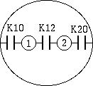
For example, if the case of a shielded 2-donductor shield in Figure 1, K10 = K20 will holds by Green's reciprocity theorem.

Fig. 1 - partial capacitance of shieded 2-conductor cable
The partial capacitance is obtained solving lenear eqation made by combinations of partial capacitance measurement.
For example, We can make following procedure for Fig.1.
  K10 = (C1 - C2 + C12) / 2
  K12 = (C1 + C2 - C12) / 2
  K20 = (C2 - C1 + C12) / 2
For general multi-conductor case, see Note 1.

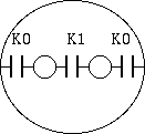
Fig. 2 - partial capacitance of shielded 2-conductor cable
Once the partial capacitances are known, easily effective capacitance can be calculate by simple parallel/resial capacirance circuit. And this is the work of cable users.
For example, if the shielded 2-donductor cable case as a microphone cable, due to the symmetry, rewriting
  K0 = K10 = K20
  K1 = K12
We can get
  differential mode capacitance = K1 + K0 / 2
  common mode capacitance = K0 * 2 (capacitance between connected 2-condictor and shield)
  capacitance between one conductor connected with anothe conductor and shield = K0 + K1
The capacitance value defined in specification is the value of 20 C 1 kHz.
For cable using material having good high-frequency characteristics in non-polar molecule, such as polyethylene, these vales are not varies with freauency and temperature. But for the cable using PVC compound and other polar molecule material, capacitance is largely depend on freauency and temperature.
6.1. Note 1 - coefficient of potential and partial capacitance
On electro-magnetic thory, relation between the potential and the charge of multi-conductor system is defined by coefficient of potential or coefficient of capacity.
Using coefficient of capacity,
  Q1 = C11*V1 + C21*V2 + .... + Cn1*Vn
  Q2 = C12*V1 + C22*V2 + .... + Cn2*Vn
  ....................................
  Qn = C1n*V1 + C2n*V2 + .... + Cnn*Vn
Compared with the partial capacitance definion, we get following relation.
  Ki0 = Ci1 + Ci2 + Ci3 + .... + Cin
  Kij = -Cij  (i != k, k != 0)
To interpret coefficient of capacity as a circuit element is difficult, but the measurement is easy. For example, we can use the following procedure.
Cij = (Ci + Cj - Ci+j) / 2
As nCr is the number of combinations to choose r from n, the number of measurements is
nC1 + nC2 = n + n!/2/(n-2)!It takes lot of work if number of conductors is incresed. But in many cases, number of measurement reduces by symmetry.
Measurement of capacitance coefficient from can be performed with a minimum step in an organized manner, at first measure the capacitance coefficient, then calculate partial capacitance is the good measurement practice.
Kouichi Hirabayashi, 2013-08-27